

How To Repair Fan Plug In On Motherbard
Motherboard Power Connectors
Every PC ability supply has special connectors that attach to the motherboard, giving ability to the organization processor, memory, and all slotted add-on boards (ISA, PCI, AGP). Attaching these connectors improperly can accept a devastating effect on your PC, including burning up both your ability supply and motherboard. The following sections detail the motherboard ability connectors used by various power supplies.
AT Power Supply Connectors
Industry standard PC, XT, AT, Babe-AT, and LPX motherboards all use the same blazon of chief power supply connectors. These supplies characteristic two main power connectors (P8 and P9), each with half-dozen pins that adhere the power supply to the motherboard. All standard PC power supplies that use the P8 and P9 connectors take them installed end to finish so that the two black wires (footing connections) on both ability cables are next to each other. Some power supplies have them labeled as P1/P2 instead. Because these connectors commonly take a squeeze that prevents them from being inserted astern on the pins on the motherboards, the major concern is getting the ii connectors in the correct orientation side by side and also non missing a pin offset on either side. Post-obit the black-to-blackness rule keeps you safe. You must take care, even so, to make sure that no remaining unconnected motherboard pins be between or on either side of the two connectors subsequently you install them. A properly installed connector connects to and covers every motherboard power pivot. If any power pins are showing on either side of the connectors, the entire connector assembly is installed incorrectly, which tin can result in catastrophic failure for the motherboard and everything plugged into information technology at the fourth dimension of ability-upward. Figure three.6 shows the P8 and P9 connectors (sometimes as well called P1/P2) in their proper orientations when connecting.
 Effigy iii.6 The P8/P9 power connectors (sometimes besides chosen P1/P2) that connect an AT/LPX ability supply to the motherboard.
ATX Primary Power Connector
The industry standard ATX ability-supply–to–motherboard main connector is the Molex 39-29-9202 (or equivalent) 20-pin ATX style connector (see Figure 3.vii). Beginning used in the ATX form factor ability supply, it also is used in the SFX grade factor or whatever other ATX-based variations. The colors for the wires listed in Table iii.3 are those recommended past the ATX standard; however, they are not required for compliance to the specification, and so they could vary from manufacturer to manufacturer. Note that I like to evidence these connector pinouts in a wire side view, which shows how the pins are bundled looking at the back of the connector (from the wire and not terminal side). This is because information technology shows how they would be oriented if you were back-probing the connector with the connector plugged in.
![]() Effigy three.7 ATX style twenty-pin motherboard main power connector, perspective view.
Effigy three.7 ATX style twenty-pin motherboard main power connector, perspective view.
Effigy 3.8 shows a view of the connector equally if you were looking at information technology facing the terminal side.
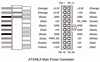 Figure 3.8 ATX/NLX 20-pin chief power connector, terminal side view.
Tabular array 3.3 ATX Main Power Supply Connector Pinout (Wire Side View)
| Colour | Betoken | Pin | Pin | Bespeak | Color |
| Orange* | +3.3V | 11 | 1 | +3.3V | Orangish |
| Blue | –12V | 12 | 2 | +3.3V | Orangish |
| Blackness | GND | xiii | 3 | GND | Blackness |
| Dark-green | PS_On | 14 | 4 | +5V | Red |
| Black | GND | 15 | 5 | GND | Black |
| Blackness | GND | 16 | 6 | +5V | Red |
| Black | GND | 17 | 7 | GND | Black |
| White | –5V | 18 | 8 | Power_Good | Gray |
| Red | +5V | 19 | 9 | +5VSB (Standby) | Royal |
| Ruddy | +5V | 20 | 10 | +12V | Yellow |
*Might have a 2d orange or brown wire, used for +3.3v sense feedback—used by the ability supply to monitor 3.3v regulation.
Notation
The ATX supply features several voltages and signals not seen before, such as the +3.3v, PS_On, and +5v_Standby. Therefore, adapting a standard LPX grade factor supply to make it piece of work properly in an ATX system, is difficult—if not incommunicable—even though the shapes of the power supplies themselves are virtually identical.
However, because ATX is a superset of the older AT standard, y'all can apply an adapter to allow an ATX power supply to connect to an older Babe-AT style motherboard. PC Power and Cooling (run across the vendor list) sells this type of adapter.
ATX Auxiliary Power Connector
As motherboards and processors evolved, the need for power became greater. In particular, chipsets and DIMMs were designed to run on 3.3v, increasing the current demand at that voltage. In improver, about boards included CPU voltage regulators designed to catechumen +5v power into the unique voltage levels required by the processors the board supported. Eventually, the high current demands on the +3.3v and +5v outputs were proving too much for the number and gauge of the wires used. Melted connectors were condign more and more mutual as these wires overheated under these loads.
Finally, Intel modified the ATX specification to add a 2d power connector for ATX motherboards and supplies. The criteria was that if the motherboard needed more than 18A of +3.3v power, or more than 24A of +5v power, an auxiliary connector would exist defined to carry the additional load. These higher levels of power are unremarkably necessary in systems using 250-watt to 300-watt or greater supplies.
This is a 6-pin Molex-type connector (meet Figure three.nine). Information technology is keyed to foreclose misconnection.
![]() Figure three.9 ATX auxiliary power connector.
Figure three.9 ATX auxiliary power connector.
The pinouts of the auxiliary connector are shown in Table 3.4.
Table 3.iv ATX Auxiliary Power Connector Pinout
| Signal | Color | Pin | Pin | Signal | Color |
| Gnd | Black | 1 | four | +3.3V | Orange |
| Gnd | Black | 2 | 5 | +three.3V | Orange |
| Gnd | Black | 3 | 6 | +5V | Red |
If your motherboard does not characteristic a mating auxiliary connector, it probably wasn't designed to consume a big amount of power, and the auxiliary connector from the power supply can be left unconnected. If your ability supply is rated at 250 watts or larger, you should ensure that it has this connector and that your motherboard is capable of accepting it. This eases the load on the main power connector.
ATX12V Connector
Power for the processor comes from a device called the voltage regulator module (VRM), which is congenital into virtually modern motherboards. This device senses the CPU voltage requirements (ordinarily via sense pins on the processor) and calibrates itself to provide the proper voltage to run the CPU. The design of a VRM enables information technology to run on either 5v or 12v for input power. Most accept used 5v over the years, but many are now converting to 12v because of the lower current requirements at that voltage. In addition, the 5v already might exist loaded by other devices, whereas, typically, only drive motors use the 12v. Whether the VRM on your lath uses 5v or 12v depends on the item motherboard or regulator design. Many modern voltage regulator ICs are designed to run on anything from a 4v to a 36v input, and so it is up to the motherboard designer every bit to how they volition be configured.
Although most motherboard VRM designs up through the Pentium III and Athlon/Duron use 5v-based regulators, a transition is underway to utilise 12v-powered regulators. This is considering the higher voltage will significantly reduce the current draw. As an example, using the same 65W AMD Athlon 1GHz CPU, you cease up with the levels of draw at the various voltages shown in Table 3.v.
Tabular array 3.five Levels of Describe at Various Voltages
| Watts | Volts | Amps | Amps at 75% Regulator Efficiency |
| 65 | ane.8 | 36.i | — |
| 65 | 3.iii | nineteen.7 | 26.3 |
| 65 | v.0 | 13.0 | 17.3 |
| 65 | 12.0 | five.4 | 7.2 |
Equally you lot can see, using 12v to power the scrap results in just 5.4A of draw, or seven.2A assuming 75% efficiency on the part of the regulator.
So, modifying the motherboard VRM excursion to apply the +12v ability feed would seem simple. Unfortunately, the standard ATX 2.03 power supply design has merely a single +12v pb in the main power connector. The auxiliary connector has no +12v leads at all, so that is no assist. Pulling up to 8A more through a single 18ga. wire supplying +12v power to the motherboard is a recipe for a melted connector.
To broaden the supply of +12v power to the motherboard, Intel created a new ATX12V power supply specification. This adds a third power connector, called the ATX12V connector, specifically to supply additional +12v power to the lath. This connector is shown in Figure iii.x.
![]() Effigy 3.10 An ATX12V ability connector.
Effigy 3.10 An ATX12V ability connector.
The pinout of the +12v power connector is shown in Table iii.6.
Table 3.6 ATX +12v Ability Connector Pinout (Wire Side View)
| Color | Indicate | Pin | Pin | Signal | Color |
| Yellow | +12V | 3 | 1 | Gnd | Black |
| Yellowish | +12V | 4 | 2 | Gnd | Blackness |
If y'all are replacing your motherboard with a new one that requires the ATX12V connection for the CPU voltage regulator, and yet your existing power supply doesn't have that connector, an easy solution is available. Merely convert one of the peripheral power connectors to an ATX12V type. PC Power and Cooling has released just such an adapter that can instantly make whatever standard ATX power supply into one with an ATX12V connector. The upshot is non whether the power supply tin can generate the necessary 12v—that has always been available via the peripheral connectors. The ATX12V adapter shown in Figure 3.11 solves the connector problem quite nicely.
![]() Figure 3.11 ATX12V adapter from PC Power and Cooling.
Figure 3.11 ATX12V adapter from PC Power and Cooling.
ATX Optional Connector
The ATX specification also defines an optional six-pin connector. This connector has 2 rows of three pins each to provide the signals and voltages. The figurer tin use these signals to monitor and control the cooling fan, monitor the +iii.3v power to the motherboard, and provide power and grounding to IEEE 1394 (FireWire) devices.
This connector has gone through several revisions in pinout since first beingness published, and I have yet to see any motherboards or power supplies on the market that actually support information technology. In fact, the latest ATX/ATX12V Ability Supply Design Guide published past Intel states, "Details of the 2x3 'Optional Power Connector' mentioned in the ATX two.03 Specification are omitted from this blueprint guide until such fourth dimension as the signals on that connector are more rigidly divers."
Table three.7 lists the pinout of the optional connector every bit defined in the ATX two.03 Specification.
Table 3.7 ATX Optional Power Supply Connections
| Color | Signal | Pivot | Pin | Signal | Color |
| White/Black Stripe | 1394R | 4 | 1 | FanM | White |
| White/Carmine Stripe | 1394V | five | two | FanC | White/Blue Stripe |
| Reserved | vi | 3 | +3.3V sense | White/Chocolate-brown Stripe |
The FanM bespeak enables the operating system to monitor the status of the power supply's cooling fan so that it can take appropriate actions, such as shutting down the system if the fan fails.
The motherboard (under operating system control) tin use the FanC signal with variable voltages to control the performance of the power supply'due south fan, shifting it into a low power state or shutting it off completely when the system is in sleep or standby style. The ATX standard specifies that a voltage of +1v or less indicates that the fan is to shut downwardly, whereas +10.5v or more instructs the fan to operate at full speed. The system designer can define intermediate voltages to operate variable-speed fans at various levels. If the power supply does non include a variable-speed fan circuit, whatever voltage level higher than +1v on the FanC signal is interpreted every bit a command to run the fan at its full (and simply) speed.
The 1394 connectors are for powering an optional IEEE-1394 (FireWire or iLink) bus on a motherboard. The 1394V pin provides voltages from 8v to 40v to run FireWire peripherals off the bus, and the 1394R pivot is a return or footing line for this ability circuit. This separate power rail keeps the 1394 motorbus power separate from the arrangement main power to prevent interference.
NOTE
The SFX specification too defines the utilize of a half dozen-pivot control connector, simply uses information technology only to provide a fan command signal on one pin. The other five pins are all reserved for future use.
Dell Proprietary (Nonstandard) ATX Design
If you currently own a desktop system fabricated between 1996 and 2000 from Dell, you volition definitely desire to pay attending to this section. A potential booby trap is waiting to blast the unsuspecting Dell arrangement owner who decides to upgrade either the motherboard or ability supply in his system. This subconscious trap can cause the devastation of the motherboard, power supply, or both! Okay, now that I have your attention, read on....
Equally those of yous who have attended my seminars or read previous editions of this book will know, I take long been a promoter of industry-standard PCs and components and wouldn't think of purchasing a desktop PC that didn't accept what I consider an manufacture-standard grade gene motherboard, ability supply, and chassis (ATX, for instance). I've been down the proprietary road before with systems from Packard Bong, Compaq, IBM, and other companies that used custom, unique, or proprietary components. For example, during a momentary lapse of reason in the early '90s, I purchased a Packard Bong system. I rapidly outgrew the capabilities of the system, so I thought I'd upgrade it with a new motherboard and a faster processor. It was then that I discovered, to my horror, that LPX systems were not an interchangeable standard. Because of riser card differences, virtually no interchangeability of motherboards, riser cards, chassis, and ability supplies existed. I had what I now refer to as a "disposable PC"—the kind you can't upgrade and have to throw away instead. Suddenly, the coin I thought I had saved when initially purchasing the arrangement paled in comparison to what I'd now accept to spend to completely replace it. Lesson learned.
After several bad upgrade and repair experiences, I decided never again would I exist trapped by systems using proprietary or nonstandard components. By purchasing only systems built with industry- standard parts, I could hands and inexpensively upgrade, maintain, or repair the systems for many years into the future. I have been preaching the gospel of industry-standard components in my seminars and in this book ever since.
Of class, building your own system from scratch is one way to avert proprietary components, but often that route is more costly in both fourth dimension and money than purchasing a prebuilt system. And what systems should I recommend for people who want an inexpensive prebuilt system just one that uses industry-standard parts so it can be inexpensively upgraded and repaired later? Although many organization vendors and assemblers exist, I've settled on companies such every bit Gateway, MicronPC, and Dell. In fact, those are really the 3 largest system vendors that deal direct, and they more often than not sell systems that use industry-standard ATX class factor components in all their principal desktop system product lines. Or so I thought.
It seems that when Dell converted to the ATX motherboard form cistron in mid-1996, it unfortunately defected from the newly released standard and began using particularly modified Intel-supplied ATX motherboards with custom-wired power connectors. Inevitably, it as well had custom power supplies made that duplicated the nonstandard pinout of the motherboard ability connectors.
An fifty-fifty bigger criminal offense than simply using nonstandard ability connectors is that simply the pinout is nonstandard; the connectors look like and are keyed the aforementioned every bit is dictated by truthful ATX. Therefore, zero prevents y'all from plugging the Dell nonstandard power supply into a new manufacture-standard ATX motherboard you lot installed in your Dell case as an upgrade, or even plugging a new upgraded manufacture-standard ATX power supply into your existing Dell motherboard. But mixing either a new ATX board with the Dell supply or a new ATX supply with the existing Dell lath is a recipe for silicon toast. How do you lot like your fried chips: medium or well-washed?
Bluntly, I'm amazed I haven't heard more about this because Dell has climbed to the lead in worldwide PC sales. In any case, I figure by getting this information out I tin relieve thousands of innocent motherboards and ability supplies from instant decease upon installation.
If you've already fallen victim to this nasty circumstance, believe me, I feel your pain. I discovered this the difficult way as well—by frying parts. At first, I thought the upgraded power supply I installed in i of my Dell systems was bad, especially because the dramatic fashion it smoked when I turned on the system: I actually saw burn through the vents! Good thing I decided to cheque the color codes on the connectors and verify the pinout on some other Dell arrangement by using a voltmeter before I installed and fried a second supply. I was lucky in that the smoked supply didn't accept the motherboard with it; I can only surmise that the supply fried so speedily information technology sacrificed itself and saved the motherboard. You might non be so lucky, and in most cases I'd await you'd fry the board and supply together.
Telephone call me a fool, but I didn't think I'd have to cheque the color-coding or get out my voltmeter to verify the Dell "pseudo-ATX" power connector pinouts before I installed a new ATX supply or motherboard. You'll also find that motherboard and power supply manufacturers don't like to replace these items under warranty when they are fried in this fashion due to nonstandard connector wiring.
Dell'south official explanation for its lack of conformance to the ATX standard was, "In the mid-90s the industry moved to a higher use of 3.3v motherboard components. Dell engineers designed a connector that supported the increased use of three.3v current which differed from the industry proposed designs that we deemed less than robust." Unfortunately, this caption doesn't hold much water because the standard ATX connector incorporated three 3.3v pins, assuasive for up to 18A of electric current, and the addition of the Auxiliary Connector added two more pins with 10A of additional current. Dell's pseudo-ATX pattern had only three iii.3v pins in the Auxiliary Connector, which could supply only up to 15A to the lath. You can see that even the main ATX Connector solitary had more 3.3v current than Dell's design using two connectors!
Because its technical explanation fails to address the issue, the only other reason I can imagine it did this is to lock people into purchasing replacement motherboards or ability supplies from Dell. What makes this worse is that Dell uses virtually all Intel-manufactured boards in its systems. Ane system I have uses an Intel D815EEA motherboard, which is the same board used by many of the other major system builders, including Gateway and Micron. It's the aforementioned, except for the power connectors, that is. The departure is that Dell has Intel custom-make the boards for Dell with the nonstandard connectors. Everybody else gets near the same Intel boards, but with manufacture-standard connectors.
Tables 3.8 and three.ix show the nonstandard Dell principal and auxiliary power supply connections. This nonstandard wiring is used on Dell'south pseudo-ATX systems.
Table three.8 Dell Proprietary (Nonstandard) ATX Master Ability Connector Pinout (Wire Side View)
| Color | Signal | Pin | Pin | Bespeak | Color |
| Gray | PS_On | 11 | 1 | +5v | Red |
| Black | Gnd | 12 | 2 | Gnd | Black |
| Black | Gnd | thirteen | 3 | +5v | Red |
| Black | Gnd | 14 | 4 | Gnd | Blackness |
| White | –5v | fifteen | five | Power_Good | Orange |
| Reddish | +5v | xvi | 6 | +5VSB (Standby) | Purple |
| Carmine | +5v | 17 | vii | +12v | Yellow |
| Red | +5v | 18 | 8 | –12v | Blueish |
| KEY (bare) | — | 19 | 9 | Gnd | Black |
| Red | +5v | 20 | x | Gnd | Blackness |
Table iii.9 Dell Proprietary (Nonstandard) ATX Auxiliary Power Connector Pinout
| Pin | Signal | Colour | Pivot | Indicate | Color |
| 1 | Gnd | Black | 4 | +3.three | Blue/White |
| ii | Gnd | Blackness | 5 | +three.3 | Blue/White |
| 3 | Gnd | Blackness | half-dozen | +3.three | Blueish/White |
At first I idea that if all Dell did was switch some of the terminals around, I could use a terminal choice to remove the terminals from the connectors (with the wires attached) and merely reinsert them into the proper connector positions, enabling me to use the Dell power supply with an upgraded ATX motherboard in the future. Unfortunately, if yous report the Dell main and auxiliary connector pinouts I've listed here and compare them to the industry-standard ATX pinouts listed earlier, you'll see that not merely are the voltage and signal positions changed, but the number of terminals carrying specific voltages and grounds has changed equally well. Y'all could modify a Dell supply to piece of work with a standard ATX lath or alter a standard ATX supply to piece of work with a Dell board, but you'd accept to practice some cutting and splicing in addition to swapping some terminals effectually. Usually, it isn't worth the time and endeavor.
If you do decide to upgrade the motherboard in any Dell system purchased between 1996 and 2000, a simple solution is bachelor—only be sure you lot replace both the motherboard AND power supply with industry-standard ATX components at the aforementioned time. That way cypher gets fried, and you'll be back to having a true manufacture-standard ATX system. If y'all want to supervene upon but the Dell motherboard, you're out of luck unless you get your replacement board from Dell. On the other mitt, if you lot want to supercede only the power supply, you do accept one alternative. PC Power and Cooling at present makes a version of its high-performance 300W ATX power supply with the modified Dell wiring for near $100. The internals are identical to its manufacture-standard, high-performance 300W ATX supply (which it sells for almost thirty% less)—only the number and arrangement of wires has inverse.
Fortunately, starting in 2000, Dell switched to using industry-standard ATX power connections in its Dimension 4300, 4400, 8200, and newer systems. That means barring whatsoever other unforeseen glitches, these systems should be more easily upgradable by but replacing either the power supply or the motherboard alone. I, for one, am glad to see Dell moving back toward manufacture standardization because its systems are now more than appealing to purchase as a starting point for a system that volition exist user upgradable and repairable in the time to come.
Ability Switch Connectors
Three main types of ability switches are used on PCs. They tin be describes every bit follows:
-
Integral Power Supply AC switch
-
Front end Panel Power Supply AC switch
-
Forepart Panel Motherboard Controlled switch
The earliest systems had ability switches integrated or built directly into the ability supply, which turned the main AC ability to the system on and off. This was a uncomplicated design, but because the power supply was mounted to the rear or side of the system, it required reaching around to the back to actuate the switch. Too, switching the Ac power directly meant the organisation couldn't be remotely started without special hardware.
Starting in the late '80s systems began using remote forepart console switches. These were substantially the same power supply design as the commencement type. The only difference is that the AC switch was at present mounted remotely (usually on the front end console of the chassis), rather than integrated in the power supply unit, and connected to the ability supply via a four-wire cable. The ends of the cablevision are fitted with spade connector lugs, which plug onto the spade connectors on the power switch. The cable from the power supply to the switch in the instance contains four colour-coded wires. In improver, a fifth wire supplying a basis connexion to the case might exist included. The switch was usually included with the power supply and heavily compress-wrapped or insulated where the connector lugs fastened to forbid electric shock.
This solved the ergonomic problem of reaching the switch, but it still didn't enable remote or automated system power-up without special hardware. Plus, y'all now had a 120v Air conditioning switch mounted in the chassis, with wires carrying unsafe voltage through the system. Some of these wires are hot anytime the system is plugged in (all are hot with the organisation turned on), creating a unsafe surround for the average person when messing effectually within her organisation.
Caution
At to the lowest degree ii of the remote power switch leads to a remote mounted AC power switch in an AT/LPX supply are energized with 115v Air conditioning current at all times. Yous could be electrocuted if y'all touch the ends of these wires with the power supply plugged in, even if the unit is turned off! For this reason, always make sure the power supply is unplugged before connecting or disconnecting the remote power switch or touching any of the wires connected to it.
The 4 or five wires are color-coded as follows:
-
Brown and bluish. These wires are the live and neutral feed wires from the 110v ability cord to the power supply. These are ever hot when the ability supply is plugged in.
-
Black and white. These wires bear the AC feed from the switch back to the power supply. These leads should exist hot merely when the ability supply is plugged in and the switch is turned on.
-
Green or green with a yellow stripe. This is the ground lead. Information technology should be connected to the PC case and should aid ground the power supply to the case.
On the switch, the tabs for the leads are usually color-coded; if not, you'll find that near switches take two parallel tabs and ii angled tabs. If no color-coding is on the switch, plug the blue and brown wires onto the tabs that are parallel to each other and the black and white wires to the tabs that are angled away from each other. If none of the tabs are angled, just make sure the blue and brown wires are plugged into the most closely spaced tabs on ane side of the switch and the black and white wires on the almost closely spaced tabs on the other side.
Come across Effigy iii.12 as a guide.
 Effigy 3.12 Ability supply remote push button switch connections.
CAUTION
Although these wire color-codings and parallel/angled tabs are used on almost power supplies, they are not necessarily 100% universal. I have encountered power supplies that did non utilise the same coloring or tab placement scheme described here. I thing is sure: Ii of the wires will be hot with Air conditioning wall current anytime the power supply is plugged in. No matter what, ever disconnect the ability supply from the wall socket before handling any of these wires. Be sure to insulate the connections with electrical record or rut shrink tubing so you won't be able to bear upon the wires when working within the example in the futurity.
Equally long every bit the blueish and dark-brown wires are on the 1 ready of tabs and the blackness and white leads are on the other, the switch and supply will piece of work properly. If y'all incorrectly mix the leads, you will likely accident the excursion breaker for the wall socket because mixing them tin can create a directly short circuit.
All ATX and subsequent power supplies that utilise the xx-pin motherboard connector utilize the PS_ON signal to power upward the system. Every bit a result, the remote switch does non physically control the power supply's access to the 110v Air-conditioning power, every bit in the older-style power supplies. Instead, the power supply's on or off status is toggled by a PS_ON indicate received on pin fourteen of the ATX connector.
The PS_ON signal can be generated physically by the computer's power switch or electronically by the operating organization. PS_ON is an active low signal, meaning that the power supply voltage outputs are disabled (the system is off) when the PS_ON is loftier (greater than or equal to 2.0v). This excludes the +5VSB (standby) on pivot 9, which is active whenever the power supply is continued to an AC power source. The PS_ON bespeak is maintained by the power supply at either three.3v or 5v. This signal is then routed through the motherboard to the remote switch on the front of the case. When the switch is pressed, the PS_ON signal is grounded. When the power supply sees the PS_ON bespeak driblet to 0.8v or less, the power supply (and system) is turned on. Thus, the remote switch in an ATX-style system (which includes NLX and SFX systems also) carries up to only +5v of DC power, rather than the full 115v–230v Air-conditioning current similar that of the older AT/LPX grade factors.
Caution
The continuous presence of the +5VSB point on pivot ix of the ATX connector means that the motherboard is always receiving standby power from the power supply when continued to an AC source, even when the calculator is turned off. Every bit a result, information technology is fifty-fifty more crucial to unplug an ATX organisation from the power source before working within the example than it is on an earlier model system.

Source: https://www.informit.com/articles/article.aspx?p=31105&seqNum=4
Posted by: oliphantsperoar.blogspot.com
0 Response to "How To Repair Fan Plug In On Motherbard"
Post a Comment